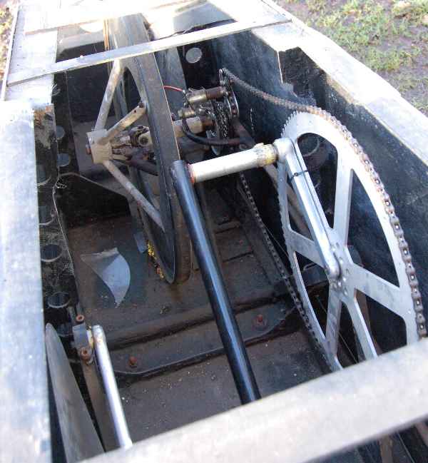
However as for production reasons our shell would have to have a flat bottom, we settled for a three-wheeler. A rearwheel-steered vehicle will never feel as safe as a front steered one (al least we have never built/riden one which comes close), so from a psychological point of view it would have to be a front steerer. Low rolling resistance is of course another necessity, and here we decided a single front wheel would be superior as it bypasses all toe-in/toe-out problems of a steered axle. A reclining seating-position gives more power than a prone position and would be more familiar to the prospective riders (car-like). (a normal cycling position is of course even better, but offers to big a profile and the C.G. would be way out.)
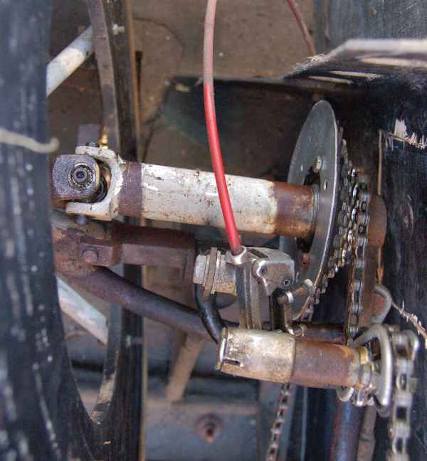
Nothing good has ever come of a chain-drive with lots of pulleys and lots of free lengths whipping around (ask Moser) so we would have to have frontwheel-drive as well.
In fact this all is starting to sound much like an Allegro or Poppy Flier, but we were not too impressed by them. For instance how can you expect Allegro's three crankshaft bearings to stay inline in what must be a flexible body-shell? And we certainly were not going to spend massive amounts of time and money (our budget was only $200) on a mould for a body shell (which the first time invariably turns out to be too short, narrow or whatever).
But then of course we had to come up with something different in order to stay within our meager budget and our self-imposed time limit.
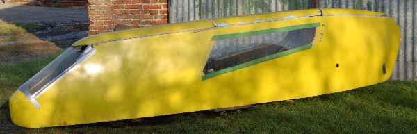
The final design is shown in the illustrations.
The body
The body of
Cafe Racer is constructed out of 1/8" plywood. 2mm plywood would perhaps
have been more appropriate but it is much more expensive. The sheets are
joined by a method known in boat-building circles as"stitch and glue".
A tornado-class catamaran is a nice example of the art. The 3-D shapes
which can be obtained are surprising, but as this was to be our first attempt
we have been rather conservative and as a result the vehicle is far to
angular to expect good aerodynamics.
A flat bottom
was used as it greatly simplifies construction by providing a convenient
measuring plane. In a borrowed livingroom the carpet was rolled back and
a couple of 4 by 4's were nailed to the floor to provide a working surface.
The floorpan was temporarely tacked in place and the bulkheads were cut
and positioned. The next step was rough-cutting the sides and stitching
them into position. Instead of thread and needle we used a powerdrill
and plastic-coated copper-wire. The plastic coating is essential as it
will not stick to the epoxy we used to glue it all together and so we are
later able to remove the wire.
Depending on
the expected loads we either used E-glass tape and epoxy or only a fillet
of resin and microballoons smeared along the joint. When cured all staples
and bits of wire were removed (much better for all planing and sanding
operations) and foamblocks for the trickiest shapes were cemented
in place. The roof of the vehicle is also made out of roofmate and it was
shaped with an electrical plane. (the actual shaping only taking minutes
in sharp contrast to the vacuum cleaning afterwards. The foamparticles
wind up with an electical charge and will stick to anything, including
windows to the chagrin of curious neighbours.)
As mastering
the art of vacuumforming great expanses of plexiglass was deemed to be
to time and cash consuming we opted for flat windows. Nowadays the windows
are not only taped but bolted in place as well as first we kept loosing
them when transporting the vehicle on a carroof.
Entry is by
removing the center roofpanel.
Performance
Vehicleweight
is a rather disappointing 40 kgs but we have an excellent professional
paintjob (Courtesy of EBAG-trucks) which surely weighs 5 kgs!
And although
low weight is very handy when storing or transporting the vehicle our computersimulation
points out that minimal weight is not all that important.
Handlingwise
our vehicle turned out to be a disappointment. From day one it handled
fine so we had to shelve our envisaged development program.
At the European
Championships we came second with a totaly untested vehicle and a mediocre
rider. Upcoming heavy sidewinds spoiled our last runs and finally finding
top-gear means little when you lift a wheel in the traps. So in the end
we only managed 82.16 against the experienced Gerhard Scheller's 92 in
the Gronen Vector.
Subsequent testing
at the Oldenburg University (BRD) by prof. Falck Riess and Rainer Pivit
revealed a stunning CDA factor of 0.110 ± 0.016 (m2), which translates
into a dragfactor of around 0.27. The rolling resistance was rather better
with .0446 ± .0024, especially when one considers the mediocre quality
of the wheels involved.
Our drag-factor
(measured by averaging 10 decellerations in the corridors of the university)
is in marked contrast to claims madeby everybody else, Gronen for instance
claiming 0.07. In our opinion this justifies our conclusion that to go
fast, you first of all need a good handling vehicle. It also probably means
that some claims are perhaps slightly optimistic.
Notes
CafeRacer was
originally build with two 28" wheels in the rear with a upwards sloping
tunnel in between, so in fact the vehicle appeared to have two tails. This
proved to be an aerodynamic mess and the wheels probably never tracked
.We only managed 60 kph and with tufts and video we found a large mass
of stagnant air around the tail. So two days before the championship we
converted to two 20" wheels and a normal tail-configuration
With our construction this was not much more involved than cutting through the glass tape, bending the panels in the required shape and making a new bulkhead and glueing on another block of foam. We didn't even had to disturb the paintjob ,some small touching up on the morning before the race being all that was needed. It did however impose some logistic problems as it meant that we had to go racing with two trikes and a twowheeler, and only six wheels to share between them!
Bolting the shoes to the pedals was another bad idea, which turned out to be very tiring when waiting. We soon converted to the system as used in the Elgar Clip trick pedal . Our version is however three times as big.